King’s retail park, Valjevo
Installation method
Technical installation conditions for loading ramps
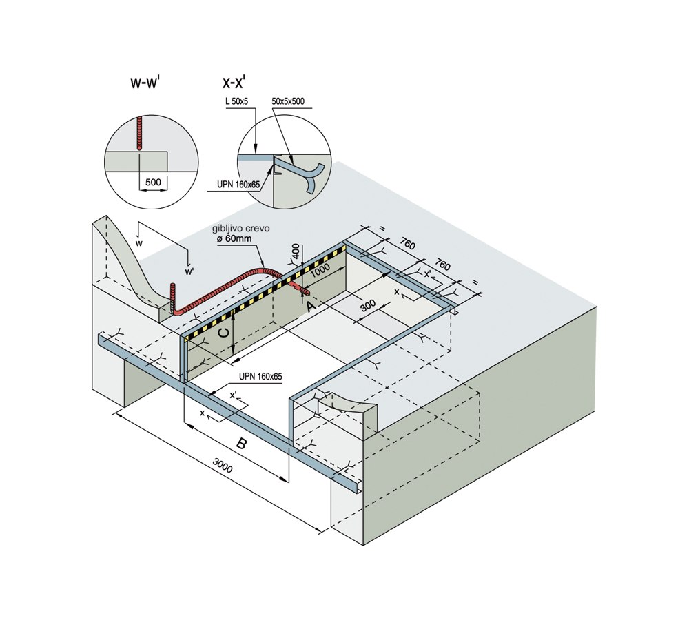
In the upper edge of the wall of the pit made of reinforced concrete, the inverted L profile is firmly installed, on which the ramp is laid and connected by welding. The ramp is installed after concreting is completed.
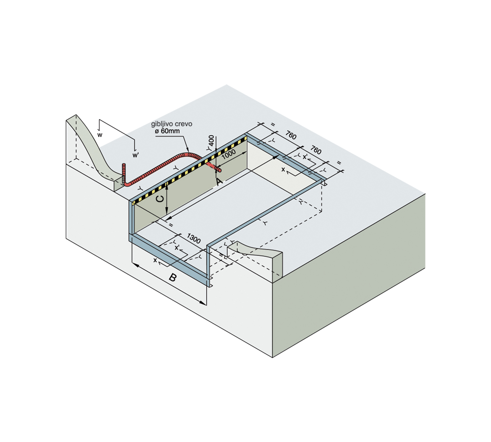
On the upper edge of the wall of the pit, a groove 100 and 150 mm wide is made of reinforced concrete, along which steel bars with a diameter of 20 mm are installed. A ramp rests on them and is joined by welding. The ramp is installed before the concreting is completed.
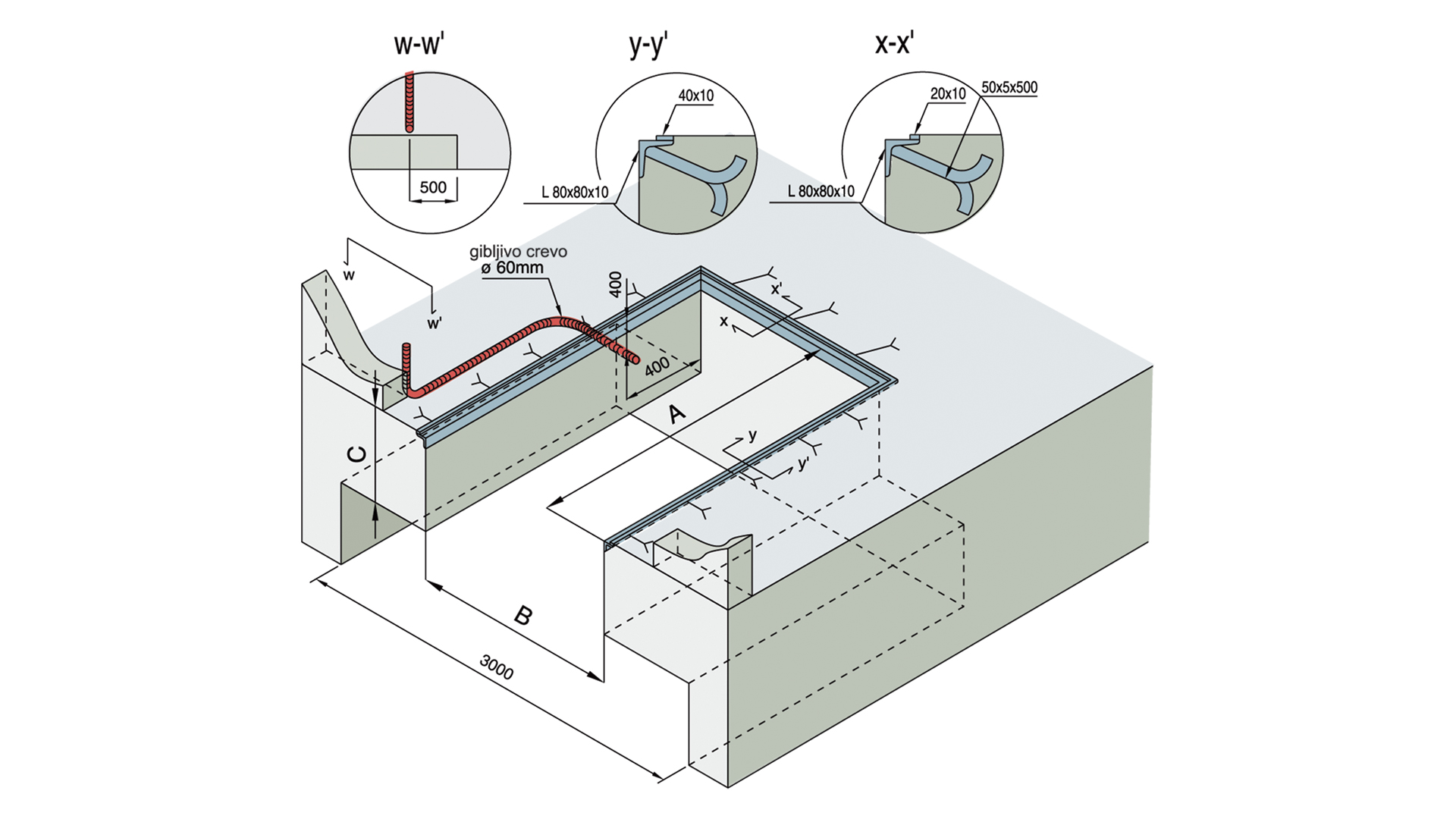
Traditional installation system in a pit made of reinforced concrete with a rim reinforced with corner, upper and lower profiles. The pit can be the same depth as the ramp or with space below, to accommodate the electro-hydraulic drive of the ramp.
The ramp bearing is built into the concrete, and the ramp is connected to the bearing by welding, at the end of concreting.

| Dimensions of type 1 and 2 pits (in mm) | ||||
| ramp width | 2000 | 2000 | 2200 | 2200 |
| ramp length | 2500 | 3000 | 2500 | 3000 |
| pit length „A“ -0 +10 mm | 2500 | 2000 | 2500 | 3000 |
| pit width „B“ -5 +5 mm | 2070 | 2070 | 2270 | 2270 |
| minimum pit height „C“ | 550 | 550 | 550 | 550 |
| Dimensions of pit types 3 and 4(in mm) | ||||||
| ramp width | 2000 | 2000 | 2000 | 2200 | 2200 | 2200 |
| ramp length (without tab) | 2000 | 2500 | 3000 | 2000 | 2500 | 3000 |
| pit length „A“ | 2000 | 2500 | 3000 | 2000 | 2500 | 3000 |
| pit width „B“ | 2040 | 2040 | 2040 | 2240 | 2240 | 2240 |
| pit height „C“ | 550 | 550 | 550 | 550 | 550 | 550 |